After making several Wemos D1 model, I started to thinking… “Should I’ve done that different..?”. I made a jumper selector on it, as a safety that when powered via USB, that power couldn’t go into the P1 port. One of the first test with a diode wasn’t that stable due to a too low power drop. And as my stash pcb’s where shrinking, I thought to fix this and make it better.
My first plan/design was adding a double diode to each power line (5V P1 and 5V Wemos). Yet searching for the best diode with the lowest power drop, I found this dual diode in a sot23 package. With a common cathode, this looked like the best solution.
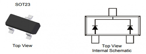
After ordering some of those diodes, I made a prototype pcb and started to test. I noticed that the power via the USB was lower than via the P1 port. It wasn’t much in difference, yet enough to figure out why. I opened the the Wemos schematic and within a few moments I found the “cause”. There’s already a diode for protection on the Wemos board itself:

Old design, new functionality
Knowing the presence of this diode, made it a lot more simpel to add protect the P1 port. I didn’t need to protect the USB port, as that’s already done per design. I took an existing board and replaced the jumper with with a new diode (low in voltage drop). Though I measured a 1.2 voltage on the P1 port (not connected) when powered via USB, this could be a lot less when connected to the P1 port, as power is then flowing the other way. First try was a succes:
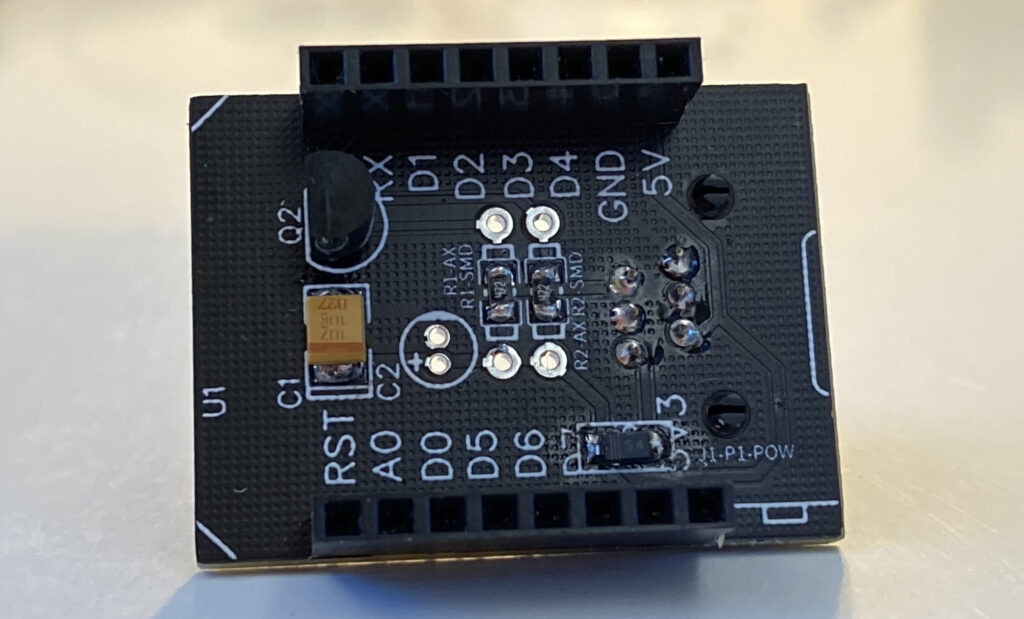
On the lower right you see the diode (left from “J1-P1-POW”, the place normally the jumper would be). Perhaps I could have placed a low resistor in series, yet I didn’t test that as this is working perfectly.
New design
I actually didn’t had to redesign a new pcb. Ditch the jumper and place a diode would have been enough. Yet with some negative experiences with the bs170 (as well with the to92, as with the sot23 package) I knew I had to use the same inverter als in the E20 ethernet module. These new inverters are better, as the can accept 5v login in and give 3v3 logic out, and they’re are cheaper to buy (and are way more difficult to solder as they have 2 more legs on the same freaking small format). The “margin” I take on the inverter, I had to give in using better capacitors. Instead of choosing between a normal or a tantalum capacitor, now I choose permanently for a tantalum capacitor, two to be exactly: 100uF and 10uF. I also added a 100nF smaller capacitor for more stability.


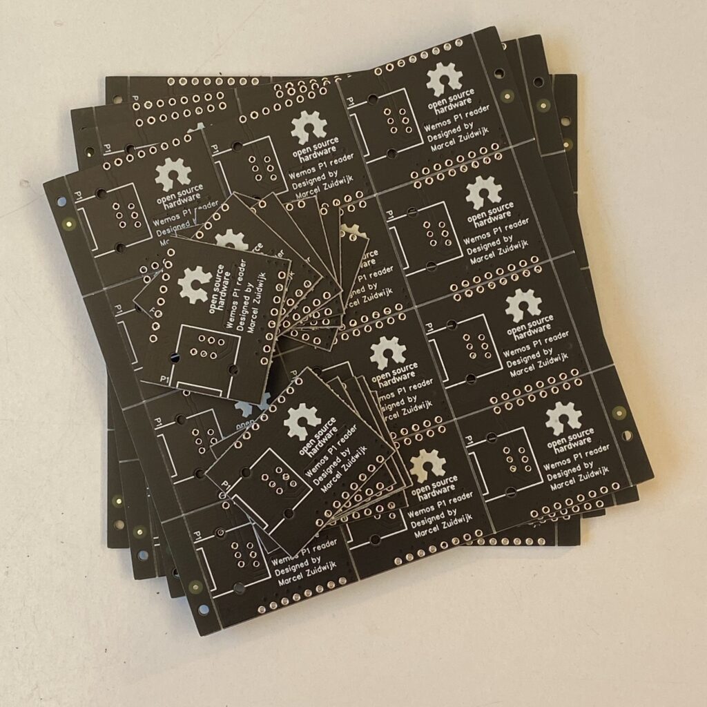
My first design had exact the same pcb measurements. All I had to do was to rearrange the components and done. When I panelized the board, I saw I was a little over the maximum size of 10x10cm. If I made the boards a little smaller, there would fit 12 pieces on one board instead of 6. I’m still a Dutchman, so squeezing all items together and I managed to get out 12 pieces (3×4). On a 5-board order, that results in 60 pieces (where normally it would have been 30). This makes the price per board halve the price it otherwise would have been.