About two years ago I had one of my first (blogged) project: Making my doorbell smart This is working perfectly since I’ve made it and many others have made it the same way, like our famous Frenck did ☺️ The problem has been all the time that an extra power supply was needed to power the ESP. Well, not anymore…
I’ve been using some well known buck converters from AliExpress for a long time. They’re cheap, small and perfect for powering ESP’s. Then the idea emerged, why not combine it all together? Making use of the doorbell transformer and get rid of the extra power supply?
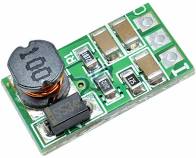
The idea was to make a hat that fit on the Wemos mini and integrate the buck converter, relay and connectors. Luckily those schematics are easy to find and I recreated the schematic and integrated that on the hat:


Proof of concept
When all components arrived, I noticed I made a little mistake: the capacitor on the input was only 16 volt, and my design is made for ~30 volt AC or DC in. With these components I made the pcb and tested it on max 15 volt in. It worked perfectly!


Now I know for sure it works, I’ll have to make some tiny adjustments to the layout (bigger capacitor and some silk text on the pcb). Once that is done, I might be thinking of selling it as a hat in my shop ☺️
ESPHome code
While my ESPHome yaml code is working fine, there was room for improvement. Looking at Frenck his code, I saw he did some nice extra’s in the code. So I borrowed some of his ideas and combined it with my needs:
esphome:
  name: doorbell
  platform: ESP8266
  board: d1_mini

wifi:
  ssid: !secret wifi_ssid
  password: !secret wifi_password


# Enable logging
logger:

# Enable Home Assistant API
api:

ota:

time:
  - platform: homeassistant
    id: homeassistant_time

text_sensor:
  - platform: version
    name: Doorbell ESPHome Version
  - platform: wifi_info
    ip_address:
      name: Doorbell IP
    ssid:
      name: Doorbell SSID
    bssid:
      name: Doorbell BSSID

sensor:
  - platform: uptime
    name: Doorbell Uptime
  - platform: wifi_signal
    name: Doorbell WiFi Signal
    update_interval: 60s

globals:
  - id: chime
    type: bool
    restore_value: true
    initial_value: 'true'

switch:
  - platform: gpio
    pin:
      number: D1
      inverted: false
    name: "Doorbell Relay"
    id: relay
    internal: true
    icon: mdi:alarm-bell
  - platform: restart
    name: "Doorbell Restart"
  - platform: template
    name: Doorbell Chime Active
    id: chime_active
    restore_state: false
    turn_on_action:
      - globals.set:
          id: chime
          value: 'true'
    turn_off_action:
      - globals.set:
          id: chime
          value: 'false'
    lambda: |-
      return id(chime);

binary_sensor:
  - platform: gpio
    pin:
      number: D5
      mode: INPUT_PULLUP
      inverted: true
    name: "Doorbell"
    filters:
      - delayed_on: 50ms
      - delayed_off: 50ms
    on_press:
      then:
        if:
          condition:
            - switch.is_on: chime_active
          then:
            - switch.turn_on: relay
    on_release:
      - switch.turn_off: relay
  - platform: status
    name: "Status Doorbell"
Bob van Mierlo
Put it in the shop and it’s sold!
Marcel
☺️ I will, but it need a little TLC before it’s ready to be sold ☺️
Peter
Very nice project. I basically did exactly the same thing by using a Shelly Uni and an AC relay. The Shelly Uni runs directly from 12V-24V AC and has two inputs and two outputs. I was able to hook the Uni directly to the doorbell supply without the need for an extra power supply. Since the Uni cannot deliver enough current for my doorbell, I had to use an additional AC relay. Since the Shelly Uni provides two inputs, I was able to hook two buttons individual. I know now whether someone is ringing at the apartment door or downstairs at the building entrance.
Please do not get me wrong, I like your solution. It is a nice piece of engineering. Congratulations.
Marcel
I understand you completely ☺️ For me, I like to see what I can make myself, and if it’s possible to make it cheap(er). Of course there are many options and ways to do it…
PM
Very nice, this combined equipment with a nice enclosure would be a nice addition to your shop.
PM
One addition: mentioning application limits on PCB could help, the relay mentions 250VAC
Marcel
Yeah, the limit currently is 16 volt due to the capacitor limitation. In the new design its replaced with a 50v capacitor. The limit will be ≤40V (limit of the buck converter). But as it is a doorbell unit, I haven’t seen/heard of a higher voltage than 24V DC in Norway.
But you’re right. Once it will be sold, I should make that clear.
Marcel
Yeah, I’m still thinking about that, maybe an existing case will do too…
Pepijn Vermeersch
I created the same sort of smart doorbell but I have 1 “issue”. My door button has a 12VAC backlight (can be 8-16VAC or 6-12VDC) powered from the bell trafo. Since the new “smart” setup I have no (or not enough) current on the GPIO pin so the LED is not working.
Do you have an idea how I can get the led working again?
I was thinking on a second 12VAC relay that is triggered by the button on the door and that just acts as the button in the above setup.
Marcel
It’s not going to work if you directly use a GPIO. Those GPIO’s using such low power that it triggers immediately. There are probably a few ways to do it but if you’re able to replace the 2-wire with a 3-wire, than that’s the easiest way.
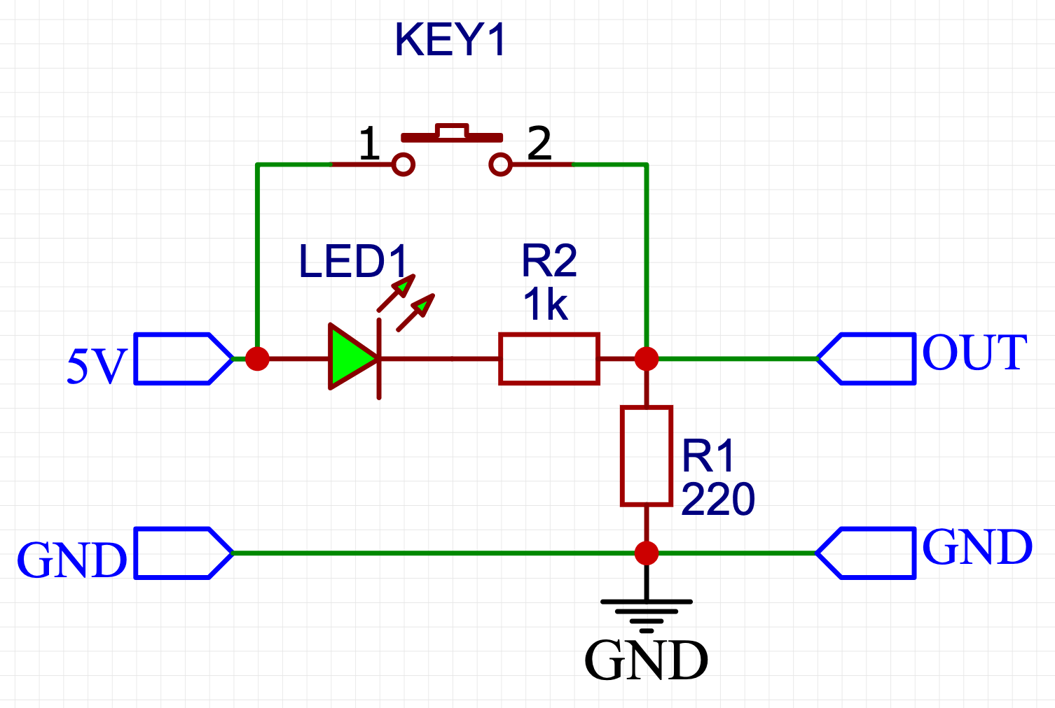
GPIO is limited to 3.3v (5v can be used). It the light requires 8-ish volt, than you need an extra circuit to handle that. For example something like this:
When button not pressed, the voltage on R1 is 5v * 220 / (1000 + 220) = 0,9v (we ignore the led for now) when the button is pressed, there will be 5v on the R1. So we created an logic low of 0,9v and logic high of 5v (maybe the low of 0,9v already triggers…)
I intentionally didn’t do that as it can give you ghost triggers…