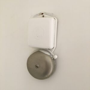
For a while I was playing with the idea to be able to mute the doorbell, and receive a notification on my phone when somebody is at the door. I have this old fashioned doorbell that’s ringing very loud:
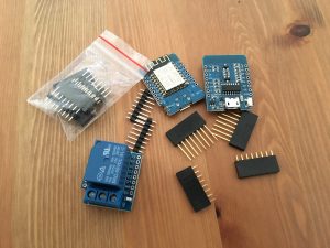
So I ordered some extra Wemos D1 mini ESP’s and a relay shield and started coding. Since I’ve discovered ESPHome, I intended to use this as number 1 choice before coding manually 🙂
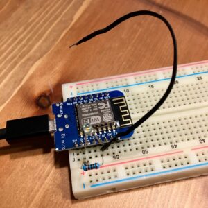
For the test setup I used a breadboard to figure out which pins to use and how the code response to it.
I’m using esphome for communication between the doorbell and homeassistant. In my design I wanted the doorbell to be able to work without interaction with homeassistant. Therefore I used the homeassistant sensor to be able to mute the doorbell. As long as this boolean is not true, the doorbell will ring. So no message to homeassistant and a message back to the doorbell, no extra delay 😉
esphome:
  name: deurbel
  platform: ESP8266
  board: d1_mini

wifi:
  ssid: "<SSID>"
  password: "<PASSWORD>"

# Enable logging
logger:

# Enable Home Assistant API
api:

ota:

switch:
  - platform: gpio
    name: "Deurbel Relay"
    id: relay
    internal: true
    icon: mdi:alarm-bell
    pin:
      number: D1
      inverted: false

binary_sensor:
  - platform: gpio
    pin: D2
    name: "Deurbel"
    #device_class: window
    filters:
#      - delayed_on: 50ms   # THIS DOES THE DEBOUNCE
      - delayed_off: 5000ms # THIS PREVENTS FROM MULTIPLE RANGS
    on_press:
      then:
        - if:
            condition:
              binary_sensor.is_off: mute # IF MUTE DONT RING
            then:
              - switch.turn_on: relay
              - delay: 250ms
              - switch.turn_off: relay
  - platform: homeassistant
    name: "Input Boolean From Home Assistant"
    entity_id: input_boolean.mute_doorbell
    id: mute
  - platform: status
    name: "Status deurbel"
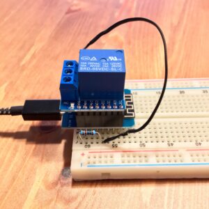
It works! Next step: assembling the Wemos and the Relay shield. The relay on the shield is connected to the D1, so that remains the same in my code. For the trigger I used the 3.3v on the D2. D2 is shorted to the ground via a resistor, and is high when pressed on the doorbell. This resister is needed to make sure that the input is only high when doorbell is pressed and is low on release.
The schematic (on multiple requests 😉)
On many request, I’ll explain the working a little more. The relay replaces the button by the door. That part is shown on the right of the schematic. Of course we need a trigger and that’ll be the button by the door. That part is on the left of the schematic.
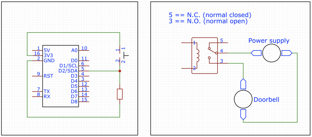
The relay
The relay has a N.O. and a N.C. That stands for Normal Open and Normal Closed. Normal open means that that pin/connector is open in the normal state of the relay (not powered). Normal closed means that that pin/connector is closed in the normal state. Therefore we need to use the normal open (N.O.) pin, so that the circuit is only closed when the relay gets power.
Using the N.C. would result in continuously ringing of the bell 😉
The trigger
In the code I use, the trigger pin is D2. When D2 is low, the doorbell button/switch is not pressed. When the doorbell button/switch is pressed, the logic state of D2 will be high. Because it is connected via the switch to the 3v3 (please do use 3v3 and not 5v!! The logic ports of an ESP is 3v3 logic).
When not pressed, the port D2 must be low. To ensure it is low (and not floating between high and low) we need to use a resistor to pull the port down.
Stan Boyd
I don’t see this Relay in Hassio, is it supposed to show up as a switch I don’t see the entity id in my states. Please let me know as I want to hook this up to a camera with button so I can get image sent to my phone. Thanks for the esphome yaml I tried a lot of things on the web but yours was the only one that worked. great work!!!!
Stan Boyd
switch:
– platform: gpio
name: “Deurbel Relay”
id: relay
internal: true
icon: mdi:alarm-bell
pin:
number: D1
inverted: false
Marcel
Hey Stan,
If you look at the code, you’ll see the option “internal: true”. That makes the switch an internal component. Internal components will not be exposed to the frontend (like Home Assistant). Only specifying an id without a name will implicitly set this to true. I made that choice on purpose. There is for me no need to make the doorbell accessible via Home Assistant. If you do want to make the doorbell make sound for your purpose, then you can remove that line (or make it false, yet I haven’t played with that option myself).
I’m glad I could help you out with my yaml code 🙂
Cheers!
bobvmierlo
Do you have any wiring schematics for this? Would like to use this for my doorbell, I’m just a noob starting using ESP’s do schematics that show how to integrate this in my doorbell system would really help me.
Marcel
Yes of course. Let me draw it for you, I’ll post it later.
Marcel
Ok, I didn’t manage to draw a sketch, I’ll will draw one and mail it to you. Yet the schematic is quite easy. It’s a Wemos D1 mini (any esp will do) and a relay shield. Note that if you use another esp, you need to find a relay fitting on that specific esp.
There is one resistor between the sensor/doorbell-switch pin and ground (to keep it pulled to the ground). Then the 3v3 goes via the doorbell switch to this pin. If the doorbell is pressed, it pulls the pin high, otherwise it stays/goes low.
The relay is the replacement switch for the doorbell. One wire from the doorbell transformer goes to the doorbell, the other via the relay to the doorbell.
That’s basically it, nothing more, nothing less…
Johnny B.
Hi Marcel,
Can you give us a drawing? I have an old school doorbell with 8V AC power coming from the adapter, how do i connect this to the LOLIN Relay Shield? NO? NC?
Please make a complete drawing with 8V input, Wemos, relay shield, chime, button etc.
Marcel
Hi Johnny B. (Johnny B. Good? 😉 )
I’ll upload a schematic, as you aren’t the first one to ask.
Give some time and I’ll place a schematic which explains the bell-part and the button-part.
Marcel
Adrian
Hi. Thanks for this detailed post. I wonder if you could help me with my scenario: I live in a building with more apartments and the cables from the button (outside the house) come to the chime inside my house with 8v AC. I cannot put that to the ESP inputs or I would fry it. I cannot modify anything outside my house. Can you think of something for this situation?
Thank you very much for all the info you share.
Marcel
Hi Adrian, there are several solutions. In your case I would suggest an optocoupler. Instead of the bell, place an optocoupler with a 10k resistor. That could switch a 3v3 with a pull up resistor to an input.
Another solution could be a power devider with two resistors (3k and 5k). That would devide the 8v in 3v over te 3k and 5v over the 5k. Yet I’m not a fan of this solution.
I hope this helps.
Mike Chorism
Marcel, I put this project to good use last weekend and got my doorbell smartened up. My only regret is losing the doorbell light. Plus I had to take out the bulb because it had pretty low resistance and was closing the circuit.
Anyway, yesterday I got a phantom doorbell ring. I did some research and found that for buttons, especially over runs where EMI interference may be picked up, it is preferred to use the doorbell button cable to connect a Ground pin with the GPIO pin instead of a 3V3 pin and the GPIO pin. It causes less interference (false triggers). Plus, I used a 10K pulldown resistor wired how you described, so I was thinking of changing that to a 2.2K (stronger) pull-up resistor to further mitigate interference.
What do you think?
Marcel
Well I didn’t have a button with integrated light. But yeah, that doesn’t work in my design. As the light closes the circuit.
If you want a ground to the doorbell line, you could inverse the whole system. Instead off the gpio pulled down to the ground and pull up when pressed. You could pull it high via a resistor to 3v3 and pull the pin down when pressed (via ground). The idea is the same, just logic whise inverted.
I hope you can do something with this.
Patrick Boerman
Hey Marcel.
Zou je mij kunnen vertellen of de slimme deurbel nog geproduceerd wordt of op de planning staat? Ik zou er graag 1 willen maar ben niet echt handig met solderen.
Groet,
Patrick
Marcel
Ik ga nu een berichtje plaatsen voor de nieuwe deurbel 😉
Jeroen
Marcel,
Een gekke vraag maar werkt dit ook met een alarm installatie?
Ik heb een aritech alarm en wil eigenlijk wanneer deze af zou gaan dat ik een melding krijg via googlehome o.i.d op me telefoon. Ik dacht om de sirene draad ook te gebruiken als puls voor een relais o.i d. Wat dit signaal vervolgens doorgeeft aan google
Ik zat even alles te lezen en denk als een simpele beldrukker een signaal kan geven, zou dit dan ook via het alarm kunnen?
Marcel
Dan zou je moeten kijken wat voor signaal het gaat. De deurbel heeft een 3v TTL input, alles daarboven sloopt de Wemos. Dan zou je met een simpele optocoupler kunnen werken, maar zit je al op zo’n afwijkend schema dat je beter iets aparts kan maken ipv dit ombouwen.
WimK
Hallo Marcel,
Zodra ik de smart doorbell v3 aansluit op de beltrafo en bel, gaat de bel aan, ongeacht of de schakelaar wordt ingedrukt of niet (zelfs niet aangesloten). Heb je enig idee waar dat mogelijk aan kan liggen? Dank alvast.
Marcel
Dat beketend dat er al iets getriggerd wordt, het eerste waar ik aan denk is dat je een deurbelknop hebt met een lampje erin. Dat gaat niet werken (lampje eruit halen is dan de oplossing).