For a long time I’ve used the common P1-USB cable which can be connected to a Raspberry Pi or any other computer. Since the last changes in my network and server setup, I had no server in the meter cupboard. Everything moved to my new office. So it was time to read out the P1 smart meter via the network. This can easily be done via an ESP32/ESP8266 over the WiFi, yet I like to connect as much via wire as possible. So the new challenge started …
For a while I had a unused Raspberry Pi in the meter cupboard. Yet due to the high writes of dsmr-reader, I had several times corrupt sd-cards. So I moved this to docker on my server. Yet the P1-USB cable wasn’t that long. Reading on the Dutch forum on Tweakers I saw how to send the data via WiFi. Below you see my “professional” setup, which worked great for a long time.
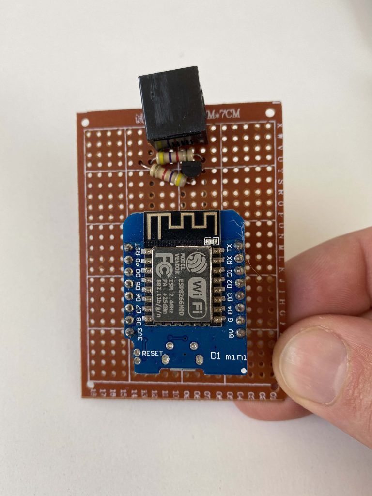
Having a switch in the cupboard, I had this idea spinning in my head to connect it via ethernet instead of WiFi. The less devices on WiFi, the less channel utilization there is.
Designing the board
I knew I could draw some power out of the P1 port. The specification reads that it can deliver 5 volts at 250mA. So I had to try that with a simple capacitor and a USR-TCP232-T2. And that worked like a charm. I used the same inverter as on the WiFi version (2 resistors and a mosfet):
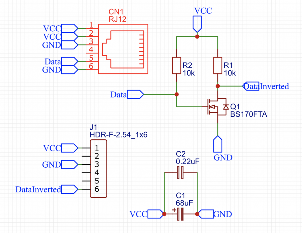
I wanted it to make as tiny as possible to make an add-on for a USR-TCP232-T2. Therefor I used only SMD. And boy did I regret choosing the sot-23 package, that it freaking small for hand soldering 😂 Once everything was placed in the schematic, it was time to design the pcb:
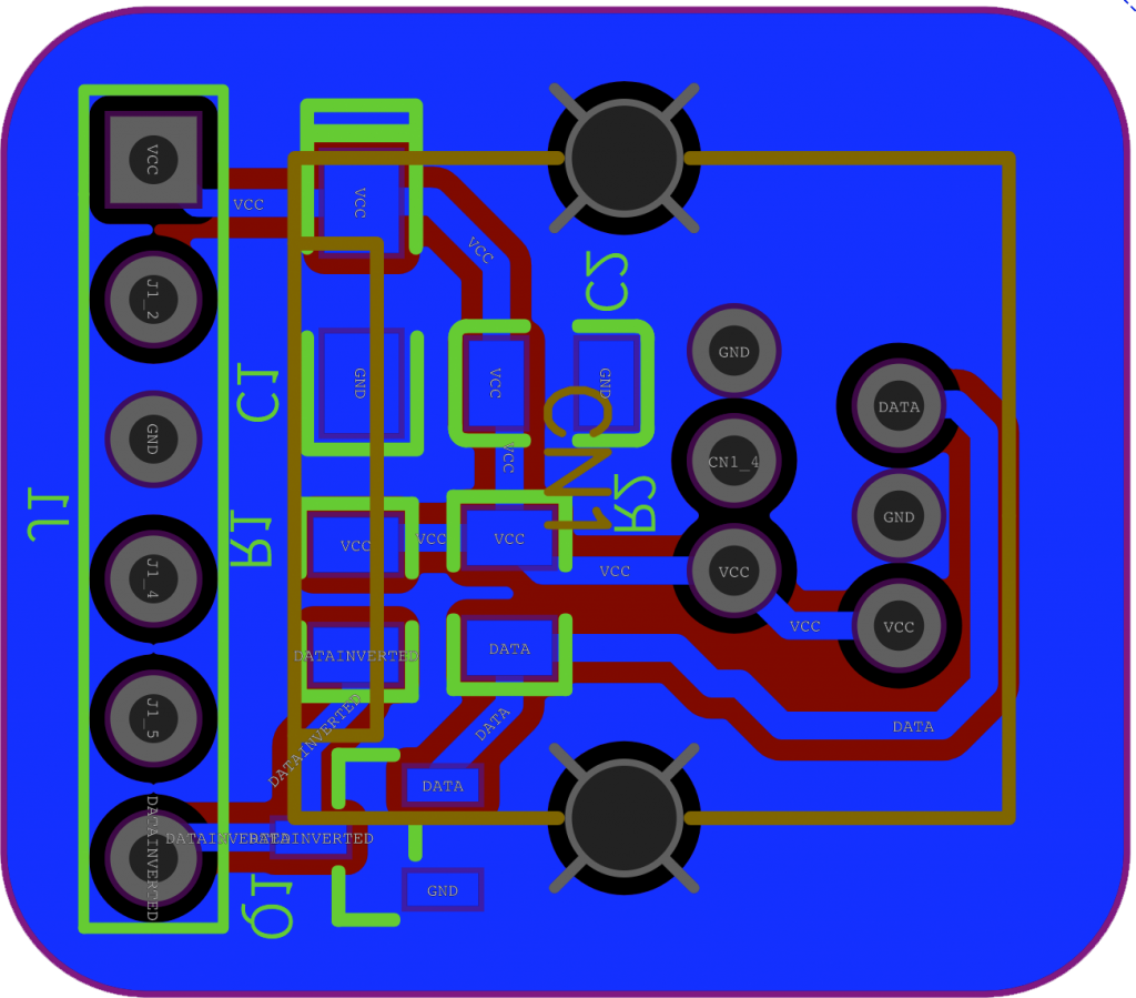
I use either KiCad or EasyEDA for designing PCBs. In this case, I used EasyEDA. I had to create the RJ12 footprint myself, as it wasn’t in the library. It looked ok to me and the order was made easily at JLCPCB. I only needed one, yet 5 pieces was more expensive than 10 and 30 was the same price as 10. So I ordered 30 off them for only $ 5,00.
Two weeks later…
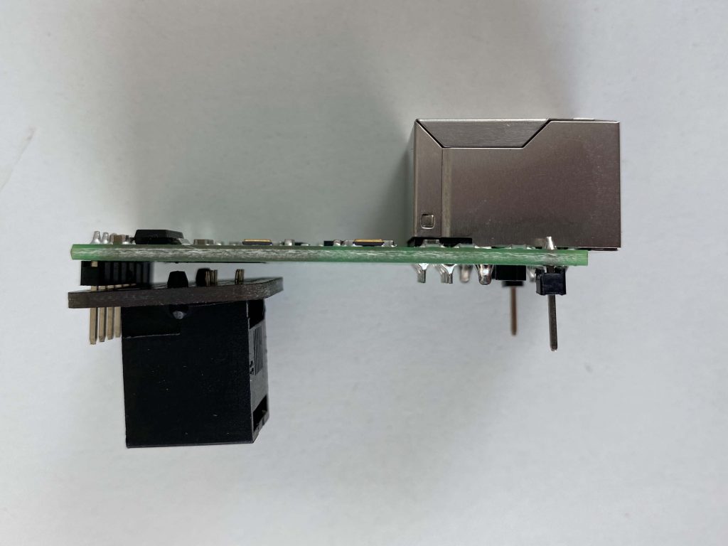
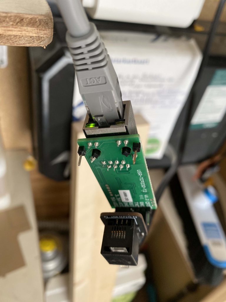
Finally, some orders came in, including the EthP1. I immediately assembled one to test it out. There was 1 design flaw. This is how I wanted it to be:
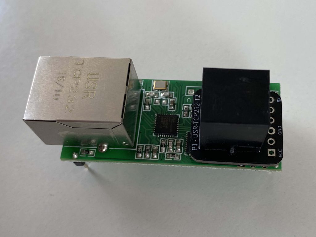
And I got the pinheaders reversed. So this is the only way it works now:
Well, I can live with that. Though if it would be mass production I would definitely change that. The RJ12 footprint was perfect, it fits perfectly. So time to solder the components:
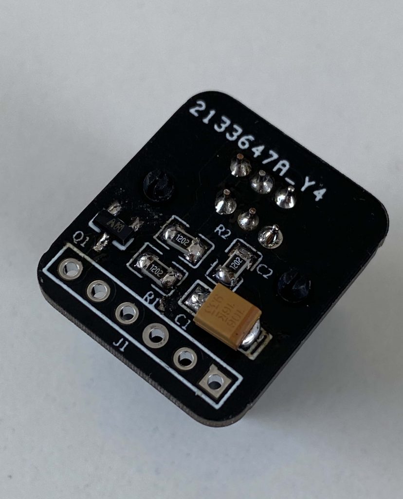
And yeah, C2 should be a small caps, yet I placed a resistor on it 😂 (it’s gone now).
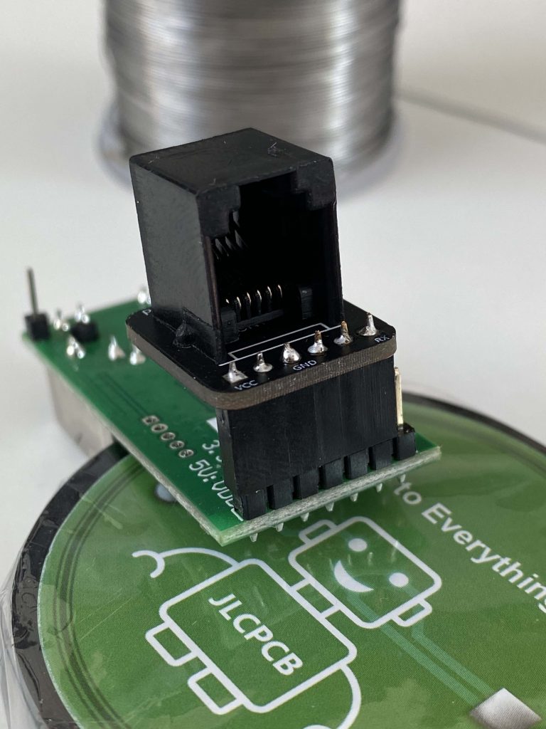
With the header soldered on, it was time to test it.
It worked perfectly. Powered via the P1 port, it now spits all data via a telnet session to my dsmr-reader docker container. One WiFi device less. Perhaps some overkill. But it was fun designing and building it. Can’t wait for my other projects to arrive and start building.