When I ordered the USR-TCP232-T2, I also did order some other ethernet modules to experiment with: The Eport E20. These looked better than the USR’s so I thought just try them to see how they work. And so the story began 🙂
Back to the drawing board (v2)
While designing at the same principle, I had to make some adjustments. This module doesn’t work on 5v, like the USR’s do (5v and 3v3 both). They only work at 3v3 and had to make therefor a 3v3 rail in the design. I used a very simple yet effective design:
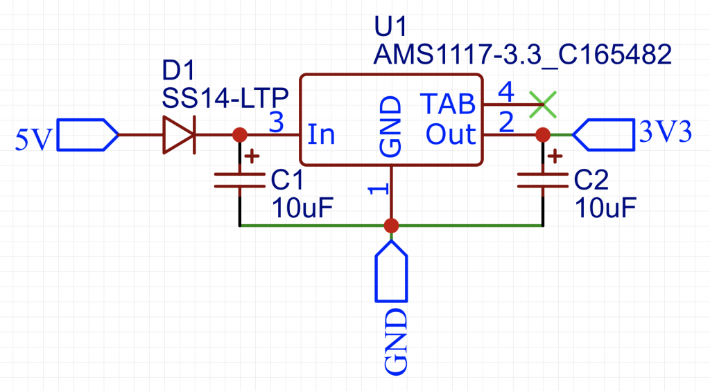
Based on the same inverter and the power supply for the Eport E20, the design was made within 30 minutes. Now I had two versions: USR and E20. I noticed that my choice between those two would be most definitely the E20. This for 3 reasons:
1) E20’s are easier to get on AliExpress
2) There was a design flaw in the USR model (P1 header on wrong side)
3) The USR comes with a fixed ip (192.168.1.7) as factory setting, which I had to change to DHCP. The E20 by default had DHCP.
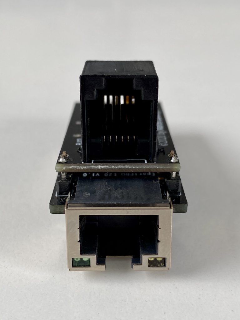
This is how version 2 looked like, much better if you’re asking me:
Version 2.1: redesign
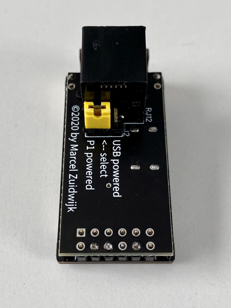
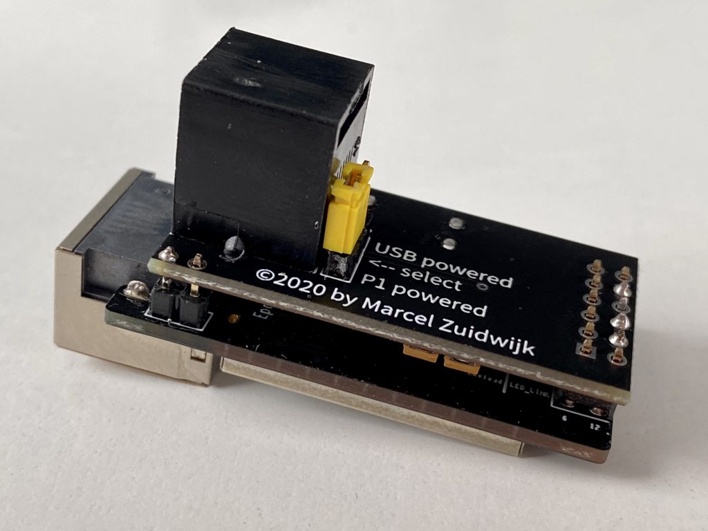
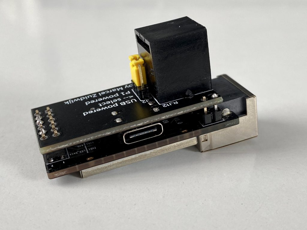
After selling about 20 of them, I noticed that there was a demand voor external powered modules. Users with older P1 meters (2, 3 and 4) couldn’t use these modules as the meter doesn’t supply enough juice on the P1 port. Because of the current design, I thought about making a simple power injector to overcome that, yet that was out of the question as that wouldn’t be a pretty design.
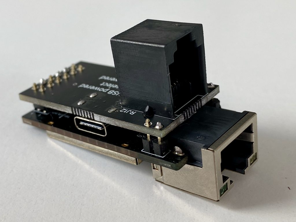
I knew I had to make a version with an USB header on it, to comply on the demands. I’m not making these as a product. Yet I want them to be usable for any P1 meter. After a short conversation with Quindor I knew I had to choose for USB-C connectors. His argument: why use old standards, as you’re designing for a future product? I had to agree with that. Besides that, there are like so many different micro-usb footprints, while the usb-c footprint is the same for most of them, what makes it easier for me to design without waiting for the connectors.
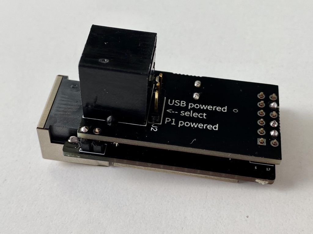
Next challenge was: how to prevent from usb-power getting into the P1 port and visa versa. I tested it with diodes, yet the power drop was a little too high for me, so I choose the old fashion jumper solution. Set the jumper for your own use.
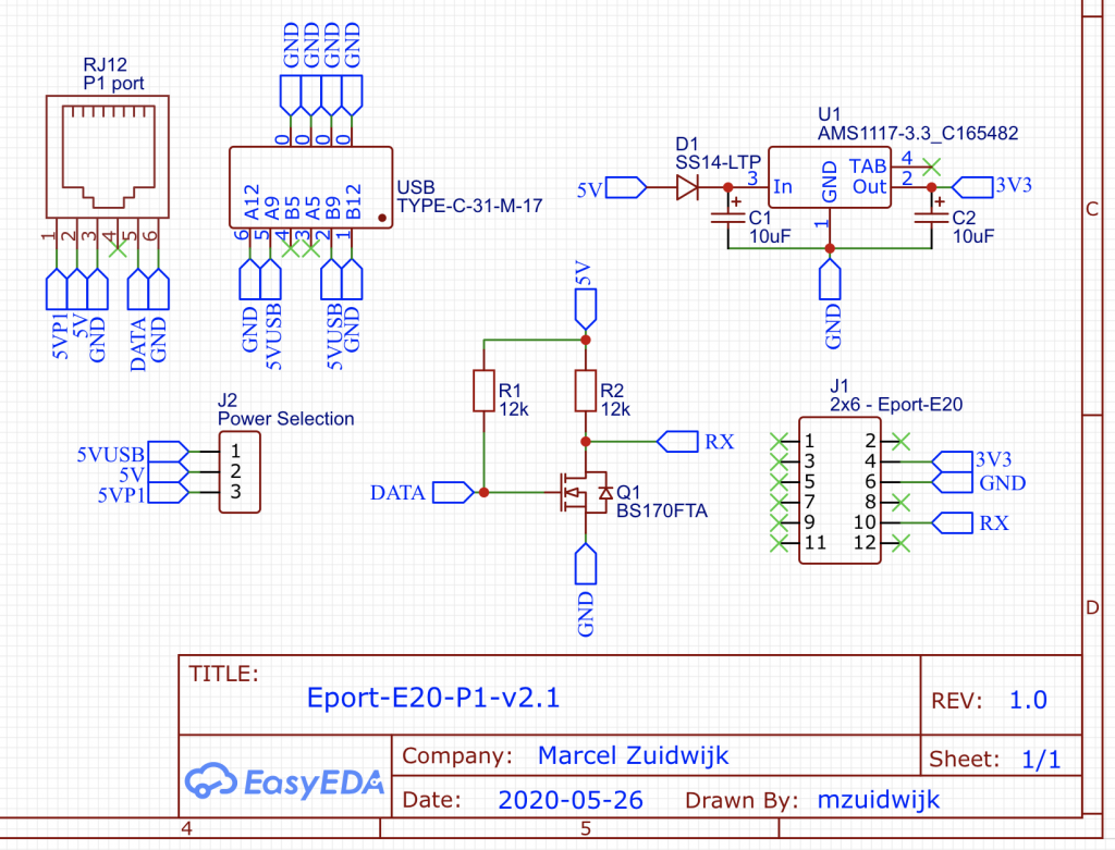
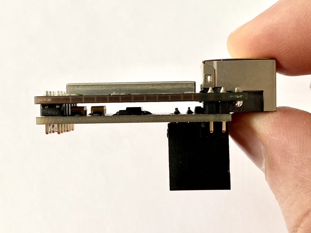
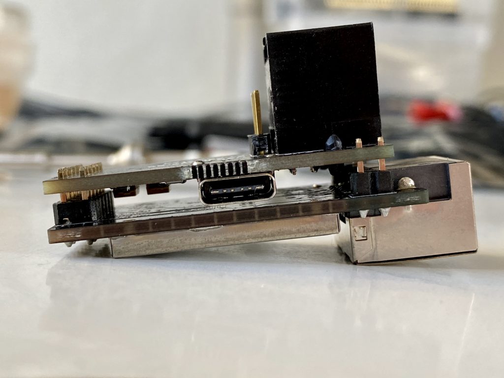
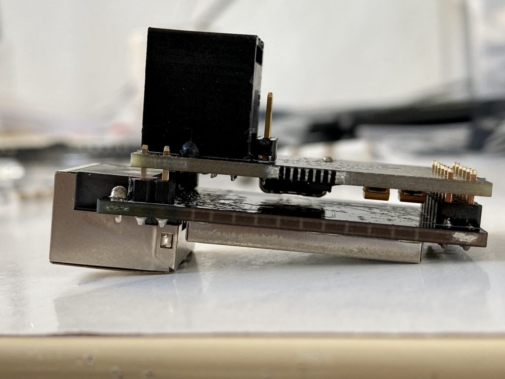
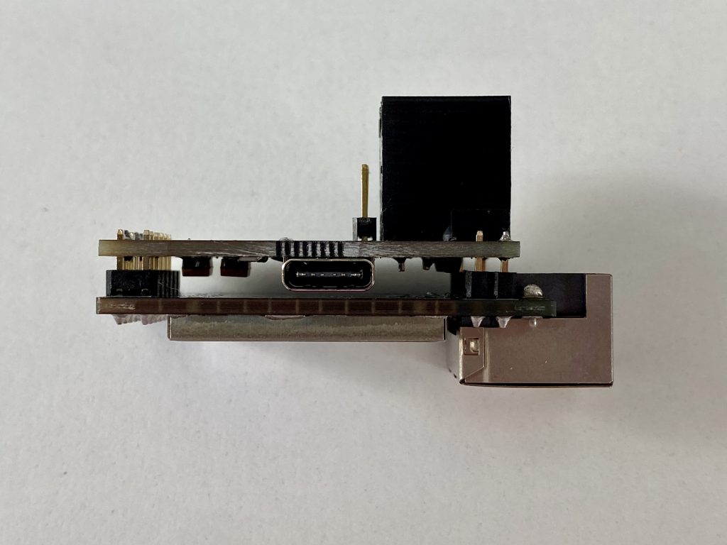
The design was the same as v2, only with an USB-C connector and a 3-pin header added. Luckily there was enough space between my pcb and the E20, so no problem with finding a spot for the USB-C header:
Looking at the date of the design, May 25th 2020, that is about 2 months ago. Darn, I have to update my website more often 😂
While I was experiencing some issues with some of the delivered products, I figured out that the cause was a faulty mosfet. I guess (I hope) that is because of a bad batch mosfets. Though I only used the more expensive parts of Farnell, I guess that can happen too. Stil, while having enough pcb’s on stock, I wanted to try a different approach. Use a logic inverter instead of the mosfet (which works very fine). I also wanted to add some more capacitors, just for stability. So you probably guess it already … there came version 2.2 …
Version 2.2
I saw this single channel inverter online, the SN74LVC1G04DBVR. It had some advantages which I wanted to use. The main advantages are:
1) high logic input voltage support (I have a 5 volt from the P1 port)
2) logical output voltage, same as vcc, so I can control what I want (3v3)
Most ESP’s are forgiving when using 5v ttl on 3v3 ttl input. Yet I didn’t know how the E20 is protected against that. Due to the high resistance I used, that wouldn’t be any problem. Than again, this gave me the opportunity to straiten that out in my design.
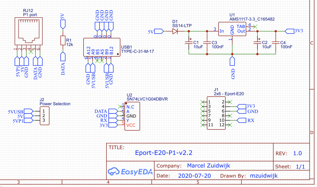
Again, based on the same design, I removed the old inverter and placed the new inverter. I had to keep one resistor as that is required for the pull-up of the internal optocoupler (dataline). The print is the same format, as it had to fit on the E20 pinout.
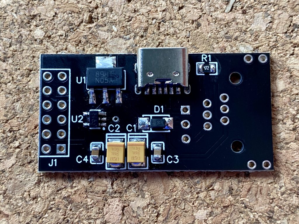
I knew that SOT23-3 is quite difficult to hand solder, yet I didn’t though that a SOT23-5 package would be a lot more “pain in the a..” to solder. Thank God for flux. I recently ordered flux to make sure the USB-C headers are soldered correctly. This came out very handy for those tiny little SOT23-5 packages 🤪😆
I’m very pleased with this new version. Same footprint, only designed better (and learned from the past).
While writing this blog, I’m already busy with some new changes and modifications, so stay tuned …
fhoornaert
Beste Marcel,
Indrukwekkend wat je allemaal in elkaar hebt geknusteld en welke passie je steekt in deze projecten.
Ik heb zelf een Sagemcom Siconia T211 (https://www.fluvius.be/nl/thema/meters-en-meterstanden/handleidingen-digitale-meter) aan de muur hangen, maar helaas geen mogelijkheid om die serieel uit te lezen. Aangezien m’n netwerk switch er net naast hangt, lijkt het me ideaal om te kiezen voor een toestel die het serieel signaal gewoon op het netwerk kan zetten, zodat ik het aan de andere kant gewoon van het net kan halen.
Vandaar de vraag, heb je nog P1 Ethernet devices v2.2 (E20 variant) te koop, en via welk kanaal kan ik die bestellen ?
Mvg,
Frederic
Marcel
Hey Frederic,
Eerlijk gezegd heb ik (nog) geen ervaring met Belgische meters. Maar toevallig heb ik verleden week een WiFi variant naar iemand in België verstuurd (nog niet werkend, het schijnt dat de P1 poort eerst geactiveerd moet worden).
Al lees ik dat de meters voldoen aan ons Nederlands concept conform DSMR 5.0.2 (https://www.fluvius.be/sites/fluvius/files/2020-03/1901-fluvius-technische-specificaties-gebruikerspoorten-digitale-meter-nl_0.pdf).
Ik heb ruim voldoende printjes liggen, maar ik wacht nog op een levering van de E20’s. Ik kan je er dus nu niet gelijk een sturen, maar ik verwacht deze binnen een paar weken binnen te hebben, als je geïnteresseerd bent, kunnen we per email contact houden. Ik zal je een mailtje sturen met alle gegevens, dan heb je ook gelijk mijn e-mailadres 🙂
Gr,
Marcel
Peter
Hi Marcel
I also have an Sagemcom Smart Meter is there a way to order your devices? Since I’m not sure if I could get a LAN Cable to the Smart Meter, I would be interested in both versions WLAN and LAN. Is there a way to order both?
Thanks
Peter
Marcel
Hi Peter, yes, no problem.
I’ll send you an email for further details 😊
fhoornaert
Hi Marcel,
The postman just passed by, with a parcel from the Netherlands 😉
The P1/E20 has survived the trip, and is now connected.
Initial findings :
* unpacked the new toy, connected to network switch & P1 port sagemcom T211 (Siconia)
* panic because the controller does not receive power, while the P1 port should supply power to your PCB.
* switched jumper to external power supply, hooked up a phone charger to the USB port of the PCB, and network cable to the switch
* YEAAAH : new device “P1-EPORT-E20” visible on the network (DHCP)
* surf to http://p1-eport-e20
* Chrome asks for username & password – what could it be ???
* Found the default admin user in the EPORT E20 operation guide (http://www.hi-flying.com/eport-e20).
* Logged in to web interface, changed telnet port to 23, NTP port to 123 (default was 0)
* Telnet session opened to the controller, but no data visible, black screen remains.
* Registered with Fluvius (https://mijn.fluvius.be/)
* online request submitted to activate P1 port
* after just a few seconds I received an email that I could activate the ports online
* Manually activated P1 port in Fluvius portal
* YEAAAH : data immediately pops up in the telnet session !!!
* Disconnected all cables from P1 controller changed jumper to “power from P1”
* Reconnected all cables and P1 power supply now works correctly as expected, apparently because when the data port is opened, the power is put on the port as well …
Thank you for the fast service and for your fantastic work !
Marcel
Be careful with changing the telnet port. Because the admin telnet is disabled as the tcp server is running on that port.
I should add more information about this. Yet wasn’t able to free some time for that (sorry 😉 ).
I’m glad you’ve received it quite quickly.
Also I could have told you to enable the p1 port as another Belgium user had the same. Yet I thought you as developers already knew that (assumption is …).
Well glad to read you’ve figured it all out, otherwise you would know how to reach me 🙂
Patrick
Dag Marcel,
Ik ben geïnteresseerd in de WLAN en LAN modules voor België.
Kan je mij de bestelprocedure doormailen?
Heb je ervaring met het gebruik van modbus tcp op de Eport E20?
mvg, Patrick
Marcel
Hoi Patrick, ik zal je even mailen 🙂
Thomas
Ik ben ook benieuwd hoe ik de Eport E20 (LAN) kan uitlezen via modbus TCP
Marcel
Hey Thomas, ik ben zelf niet bekend met modbus. Ik wil het best voor je testen, maar dan mag je mij uitleggen hoe ik dat kan testen 😉 Inmiddels zit ik al op versie 3.3. Deze versie is hetzelfde als v3.2 maar dan volledig geassembleerd vanuit jlcpcb. Je kan de documentatie van de ethernet module vinden op hun website.
Laat me even weten of je er achter bent gekomen, of als ik het misschien kan testen 🙂
Gr,
Marcel
Thomas
Dag Marcel!
Modbus TCP was maar een voorstel omdat ik zag dat dit ondersteund werd.
maar ik vind maar zeer weinig informatie terug over hoe dit dan zou moeten geconfigureerd worden.
Ik wil namelijk via Node-Red de data binnen lezen.
als dit op een andere manier dan modbus kan is dit ook goed voor mij.
https://flows.nodered.org/node/node-red-contrib-smartmeter
Groeten,
Thomas
Marcel
Standaard stel ik telnet in (via tcp server, telnetd kan ook). Als Node-Red data via een tcp-socket kan uitlezen, moet dat geen enkel probleem zijn.
Ik ben niet zo thuis in Node-Red, maar zie op GitHub staan dat het met tcp moet kunnen verbinden.
Eric
Hi,
I would like to know if your module can be accessed as modbus tcp for reading the values of the P1 connector.
Otherwise how can i read the date from a raspberry thru network?
Marcel
Hi Eric, if you want the full details and specifications, please look here. There you can find all the details about the Eport E20. I use tcp server (telnet) for reading out the data.
Eric
Ok,
Could you please send me info about buying the WLAN and/or LAN modules?
Can i also exploit the D1 connector as well?
Eric
Hi Marcel,
Thanks for the information,
In my case LAN and WLAN could be a solution.
So can you send me more information for buying these models?
Are they exploit only the P1 connectoror alos the D1 one?
Marcel
Hi Eric, I will email you all the details and options.
Marcel
I’m writing you an email right now 😉 The answer is that I only use the P1 port, as that is ment to be for consumer use.
Kevin Stokell
Hi Marcel,
I would be interested in buying one of you LAN modules for the P1 interface on my new smartmeter. I live in Den Haag in the Netherlands and “Stedin” have recently installed the “LANDIS+GYR E360” and “LANDIS+GYR G350″meters, can you confirm that these meters are compatible with your interface and if so how I can get one?
Regards,
Kevin
Marcel
Hi Kevin, I’ve already responded to you via Tweakers (where you’ve send me a dm). I will reply to you by e-mail 🙂
Amir Aryanpour
Hi Marcel
can you pls confirm whether the SlimmeLezer is compatible with Landis gyr meters?
regs
Amir
Marcel
Yes, can confirm that. If your meter is DSMR 5, it will be powered from the P1-port, if you’re having DSMR 2, 3 or 4, it needs extra power via micro usb.
fhoornaert
Hey Marcel,
Ik heb je P1 – E20 variant (v2.2) nu een 5 tal maanden in gebruik in productie, naar alle tevredenheid.
Qua PCB design zaten in dat model de RJ12 & RJ45 poort nog aan dezelfde kant van de print.
Ik zie dat je ondertussen in een nieuwe versie ze tgenover elkaar hebt gezet, wat net iets beter zou passen in onze Belgische digitale meters.
Mooie product evolutie.
Tijdens de originele ontwikkeling van m’n eigen integratie, ben ik tegen 1 major probleem aangelopen : Aangezien ik elke 5 seconden een meting opsla in een MariaDB database, om die te tonen op een Grafana dashboard (https://fhoornaert.duckdns.org/grafana), liet ik de TCP/IP verbinding tussen m’n applicatie server en jouw P1 E20 continue open staan.
Na een 20-tal uur gaat de verbinding echter steeds verloren.
K’dacht eerst dat dat lag aan m’n implementatie, maar later gemonitored via een TCP/IP packet monitor en Putty als client, en die blijkt hetzelfde probleem te hebben, dus ligt niet aan m’n client, maar waarschijnlijk aan de telnet server implementatie in de P1 E20.
De firmware was de laatste versie die op deze blog stond.
Initiële pogingen om – na een connection drop – de connectie terug op te zetten bleek ook geen succes. Blijkbaar loopt er iets verkeerd in de TCP server als hij al een 20 uur open staat …
Heb er nu rondgewerkt door de polling te doen vanuit een timer die elke 5 seconden afgaat.
Bij elke trigger van de timer, open ik nu de connectie, wacht ik tot er 1 bericht met correcte CRC binnen is, en sluit ik de TCP/IP connectie.
Op deze manier loopt het nu al 5 maanden als een zonnetje.
Begin april was er even paniek toen er geen data meer binnen kwam, maar om één of andere reden was de P1 E20 al z’n instellingen kwijt. Dacht eerst aan een power-loss, maar ‘t was midden in de nacht gebeurd, en alle andere toestellen wezen niet in de richting van een power failure…
Alle parameters opnieuw ingesteld, en alles terug in orde.
Nogmaals bedankt voor jouw TOP product.
Frederic
Marcel
Hey Frederic, leuk om te horen en terug te lezen. Het verbaasd me overigens dat bij jou na 20u de verbinding vast/stuk loopt. Mijn E20 hangt al weken ongestoord zijn werk te doen (hoef niet meer te ontkoppelen om te testen nu ik een eigen test meter heb 🙂 ). Misschien is het de manier waarop de verbinding gemaakt wordt? Ik gebruik zelf dsmr-reader en die hoef ik nooit te herstarten. Je kan eens proberen te spelen met de instellingen onder “Communication Settings”. Ik stel standaard “TCP Server” in zodat je meerdere verbindingen kan maken. Als je daar Telnetd instelt, kan er maar 1 device connecten, maar lost misschien voor jou de kwijtrakende verbinding op?
Al met al, zeer leuk om het terug te lezen 🙂